Table of Contents
What Is Eddy Current Testing?
How Eddy Current Testing Works
The Science Behind Eddy Currents
What Can Eddy Current Testing Detect?
What Eddy Current Testing Cannot Detect
Industries & Applications
Advantages of Eddy Current Testing
Limitations of Eddy Current Testing
Eddy Current Testing vs Other NDT Methods
Equipment & Technology
Probe Types and Their Applications
Calibration and Reference Standards
Choosing the Right Eddy Current Testing Provider
Frequently Asked Questions (FAQ)
Conclusion
1. What Is Eddy Current Testing?
Eddy current testing (ECT) is an electromagnetic non-destructive testing (NDT) method used to detect surface and near-surface flaws in conductive materials. Unlike other methods that require gels, radiation or extensive surface preparation, ECT operates through clean electromagnetic induction. No goo, no radiation, no part destruction. Just a probe, a coil and a changing magnetic field that reveals hidden problems before they escalate into catastrophic failures.
Eddy current testing was first developed in the late 19th century, but its widespread industrial adoption accelerated during the mid-20th century, particularly in the aerospace and nuclear power industries. Today, ECT is a mature, standardized method recognized by international bodies including ASTM, ISO and ASME.
The fundamental principle behind ECT is electromagnetic induction. A magnetic field is generated when an alternating current passes through a coil. That magnetic field, when brought near a conductive material, induces circulating currents within that material. Those circulating currents are called eddy currents.
ECT is uniquely valuable because it delivers immediate, real-time results. There is no waiting for chemical developers, no film processing, no couplant drying. An operator that’s trained can scan hundreds of feet of tubing or dozens of fasteners per hour, marking defect locations instantly and moving to the next inspection point.
This method is widely adopted across aerospace, power generation, automotive, petrochemical and metal production industries precisely because it balances speed, accuracy and cost-effectiveness better than almost any other surface inspection technique.
2. How Eddy Current Testing Works
Here is the science explained in simple terms.
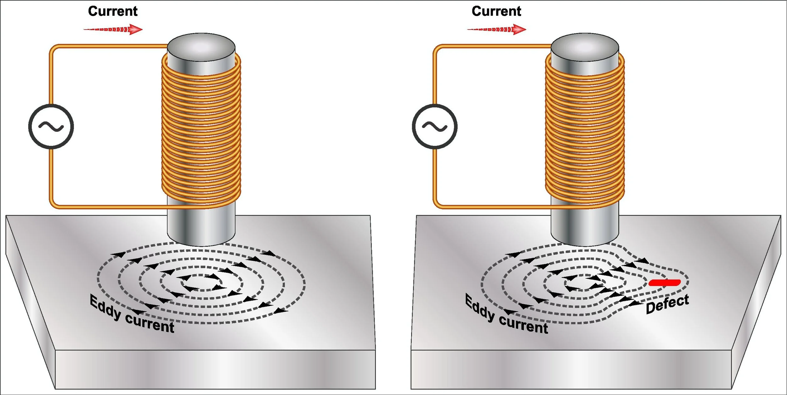
An ECT probe containing a wire coil is connected to an instrument that generates alternating current. As that alternating current flows through the coil, an oscillating magnetic field is created around the probe tip. Small circulating loops of electrical current are induced inside the metal when that magnetic field encounters a conductive material. Those are the eddy currents.
Those eddy currents generate their own opposing magnetic field, which pushes back against the probe's original coil. The instrument continuously measures this interaction.
In a uniform, defect-free material:
The eddy currents flow in regular and predictable patterns.
The opposing magnetic field remains stable.
The instrument displays a steady, repeatable signal.
When the probe encounters a crack, corrosion or thickness change:
The eddy currents are forced to detour around the discontinuity.
Their flow pattern changes abruptly.
The opposing magnetic field shifts.
The instrument displays that disruption immediately, typically as a signal spike, a phase change or an amplitude variation on a screen.
The operator sees this change in real time. They can mark the defect location on the part, record the signal for reporting and continue scanning.
The depth of penetration in eddy current testing depends on several factors, including the frequency of the alternating current, the conductivity of the material and the magnetic permeability of the material. Higher frequencies provide better sensitivity to surface defects but penetrate less deeply. Lower frequencies penetrate deeper but offer reduced sensitivity to very small surface flaws.
This principle is called the "skin effect." A skilled operator selects the optimal frequency for each specific application to balance penetration depth and defect sensitivity.
3. The Science Behind Eddy Currents
To truly understand eddy current testing, it helps to understand the underlying physics.
Electromagnetic Induction
When a conductor is exposed to a changing magnetic field, the magnetic field induces an electromotive force (EMF) within the conductor. That EMF drives the flow of electrical current. Because the conductor is a solid piece of metal rather than a wire, the current flows in closed loops rather than along a single path. Those loops are eddy currents.
Skin Effect
Eddy currents are not uniformly distributed throughout a conductor's cross-section, they concentrate near the surface. The current density is highest at the surface and decays exponentially with depth. This is the skin effect.
The depth at which eddy current density drops to approximately 37% of its surface value is called the standard depth of penetration. It is calculated using this relationship:
Penetration depth is inversely related to frequency, conductivity and permeability.
In practical terms:
Higher frequency = shallower penetration but higher sensitivity to small surface defects.
Lower frequency = deeper penetration but reduced sensitivity to fine surface cracks.
Phase Lag
Eddy currents do not occur instantaneously. There is a time delay between the changing primary magnetic field and the induced eddy currents. This delay manifests as a phase shift in the instrument's signal. That phase shift contains valuable information about the depth of a defect.
Surface-breaking defects produce a different phase angle than subsurface defects. A skilled operator uses phase analysis to estimate how deep a defect extends below the surface.
Impedance Plane Analysis
Modern ECT instruments display signals on an impedance plane, which is essentially a graph showing both the resistive and reactive components of the probe coil's electrical response. Defects cause the signal to trace specific patterns on this plane. Experienced technicians recognize these patterns instantly. They can identify the presence of a defect, its type, orientation and approximate size.
4. What Can Eddy Current Testing Detect?
Eddy current testing is very effective at identifying a wide range of discontinuities in conductive materials. Below is a comprehensive list of detectable conditions.
Surface Cracks and Fissures
ECT can detect surface-breaking cracks down to microscopic dimensions. Sensitivity depends on crack orientation relative to the probe's coil windings. Cracks that interrupt the flow of eddy currents most severely (those perpendicular to the coil windings) are detected most easily.
Subsurface Corrosion
Corrosion that lies just below the surface disrupts eddy current flow. ECT can detect corrosion down to depths of approximately 2 to 5 millimeters. This, of course, depends on material and frequency selection. This makes it valuable for inspecting components under thin coatings or cladding.
Material Thinning
Wear, erosion or chemical attack that reduces wall thickness changes the eddy current response. ECT can quantify remaining wall thickness in tubes, pipes and flat plates when properly calibrated.
Heat Damage and Metallurgical Changes
Heat treatment anomalies, overheating during service or material degradation from prolonged high-temperature exposure changes the conductivity of metals. ECT detects these changes even when no crack is present.
Conductivity Variations
Differences in alloy composition, heat treatment condition or cold work affect electrical conductivity. ECT can sort mixed alloys or verify proper heat treatment by measuring conductivity values against reference standards.
Non-Conductive Coating Thickness
Paint, anodizing and other non-conductive coatings do not block the magnetic field. ECT can measure coating thickness indirectly because the coating lifts the probe slightly away from the metal surface, changing the signal.
Weld Flaws
Surface-breaking weld defects such as lack of fusion, undercut, porosity and hot cracks are detectable with properly selected probes and frequencies.
Cracks Under Fastener Heads
ECT is widely used in aerospace to inspect for cracks radiating from fastener holes. The probe is inserted into the hole or scanned across the fastener head to detect cracks before they propagate.
Cracks in Threaded Regions
Bolts, studs and threaded components develop cracks at thread roots. Specialized thread probes detect these cracks without removing the fastener from its assembly.
5. What Eddy Current Testing Cannot Detect
Understanding the limitations of ECT is as important as understanding its capabilities.
Deep Internal Flaws in Thick Sections
ECT cannot reliably detect defects deep within thick steel sections. For components thicker than approximately 10 to 15 millimeters - depending on material - eddy currents do not penetrate deeply enough. For deep internal inspection, ultrasonic testing (UT) is the appropriate method.
Defects in Non-Conductive Materials
ECT only works on materials that conduct electricity. It cannot inspect plastics, ceramics, composites (unless they contain conductive fibers), rubber, glass or wood.
Tight, Closed Cracks at Depth
A crack that is pressed tightly closed (zero gap) may not disrupt eddy currents enough to produce a detectable signal. This is more common in some materials than others.
Defects Oriented Parallel to Probe Motion
Cracks that run parallel to the direction of probe travel may not interrupt eddy current flow significantly. Inspections often include multiple scans with different probe orientations for this reason.
Subsurface Defects Beyond Penetration Depth
Defects located deeper than the standard depth of penetration for the selected frequency will produce weak or non-existent signals. Operators have to select frequencies appropriate for the expected defect depth.
6. Industries & Applications
Eddy current testing is used across virtually every industry that depends on conductive metal components. Below is a breakdown by industry.
Aerospace
Aircraft skin for cracks and corrosion
Fastener holes for cracks radiating from hole edges
Turbine blades and disks for surface cracks and heat damage
Landing gear components for fatigue cracks
Engine mounts and structural fittings
Aging aircraft inspections - widespread fatigue damage
Aerospace remains the largest single market for eddy current testing. The industry's zero-defect tolerance and need for rapid, reliable inspections makes ECT indispensable.
Power Generation
Heat exchanger and condenser tubing in nuclear and fossil fuel plants
Steam turbine blades and rotors
Generator retaining rings
Boiler tubes
Cooling water systems
ECT is the standard method for tube inspection in power plants. Bobbin probes are pulled through thousands of tubes per day, detecting pitting, cracking and wall loss.
Automotive
Engine valves for grinding cracks
Bearing races for surface flaws
Suspension components for heat treat cracks
Brake system components
Transmission gears and shafts
Welded assemblies
Automotive suppliers use ECT for 100% inspection of important safety components. Automated systems scan parts at production line speeds.
Petrochemical and Oil & Gas
Storage tank floors for corrosio
Piping for erosion and cracking
Pressure vessels
Heat exchanger tubing
Offshore platform structural components
Refinery piping under insulation
ECT works through coatings and insulation. It allows for inspections without removing protective layers. This saves significant time and cost.
Metal Production
Coiled rod and bar stock
Wire and cable
Seamless and welded tubing
Sheet and plate
Castings and forgings
Metal producers run ECT systems inline during manufacturing to find defects before shipping to customers. This prevents expensive field failures and warranty claims.
Manufacturing & Machining
In-process quality control for machined components
Welds in fabricated assemblies
Heat-affected zone inspections
Raw material verification - alloy sorting
Hardness and heat treat verification
7. Advantages of Eddy Current Testing
ECT offers numerous distinct advantages that make it a preferred method for many inspection applications.
Immediate Results
You get readings on the spot. No waiting for chemical developers, film processing, couplant drying or laboratory analysis. This real-time feedback allows decisions to be made immediately.
Single-Side Access
The probe only needs one side of the part accessible. You do not need to reach both sides of a joint, component or assembly. This is critical for inspecting installed tubing, in-place fasteners and assembled structures.
Works Through Coatings
Thin paint, anodizing and other non-conductive coatings do not need to be removed. ECT sees through them. This saves the time and cost of stripping and recoating.
Clean and Safe
No chemical cleaners, no radioactive sources, no messy couplants. Minimal consumables. No hazardous waste disposal. Operator safety risks are extremely low compared to radiography or chemical methods.
Fast and Efficient
A trained operator can scan hundreds of feet of tubing or dozens of fastener holes per hour. Automated systems inspect parts at production line speeds measured in feet per second.
Ready for Automation
ECT systems are easily integrated into automated production lines. Robots or mechanical handling systems present parts to fixed probes. Results are logged automatically and defective parts are rejected without operator intervention.
No Surface Preparation Required
Beyond cleaning heavy dirt or grease, ECT requires no special surface preparation. Grinding, polishing and chemical etching are not needed.
Sensitive to Small Defects
Properly configured ECT systems detect extremely fine surface cracks, far smaller than what is visible to the naked eye.
Quantitative Results
ECT can estimate crack depth, wall loss and defect size when properly calibrated.
Low Per-Inspection Cost
Once equipment is purchased, the cost per inspection is very low. No consumables, no film, no chemicals. Labor is the primary cost.
8. Limitations of Eddy Current Testing
Honest discussion of limitations builds credibility. Here are the key limitations of ECT.
Conductive Materials Only
ECT does not work on non-conductive materials such as plastics, ceramics, composites (without conductive fibers), rubber or glass.
Limited Penetration Depth
ECT is primarily a surface and near-surface method. It cannot inspect deep into thick steel sections. Ultrasound is the better choice for components thicker than approximately 10 to 15 millimeters (depending on material).
Probe Positioning Sensitivity
ECT signals are sensitive to probe lift-off (distance from surface) and tilt. Inconsistent probe handling produces false signals, so operator training is essential.
Reference Standards Required
ECT instruments must be calibrated on reference standards that match the material, geometry and expected defect types of the test piece. Generic standards produce unreliable results.
Signal Interpretation Requires Skill
While basic go/no-go ECT is straightforward, advanced applications (defect sizing, subsurface characterization) need a lot of training and experience. Signal interpretation is not always intuitive.
Surface Condition Affects Results
Rough surfaces, surface irregularities and edge effects produce signals that can mask or mimic defects. Some surface preparation may still be necessary.
Ferromagnetic Materials Are More Complex
ECT on ferromagnetic materials (iron, steel) is complicated by the material's magnetic permeability, which changes with composition, heat treatment and stress. Specialized probes and techniques are required.
9. Eddy Current Testing vs Other NDT Methods
Understanding how ECT compares to alternative methods helps readers select the right technique for their application.
Magnetic Particle Testing (MT)
Best For: Surface cracks in ferrous metals
Limitation: Requires ferrous materials, direct line-of-sight access, surface cleaning and often demagnetization after inspection.
ECT Comparison: ECT works on all conductive metals (not only ferrous). No demagnetization needed. No surface cleaning beyond heavy debris.
Dye Penetrant Testing (PT)
Best For: Surface-breaking flaws in non-porous materials
Limitation: Requires multiple steps: cleaning, penetrant dwell, emulsifier, developer. Waiting time. Messy consumables.
ECT Comparison: ECT delivers instant results with no chemicals, no waiting and no messy cleanup.
Ultrasonic Testing (UT)
Best For: Deep internal flaws, thickness measurement, large cross-sections
Limitation: Requires couplant gel or water. Surface must be accessible and reasonably smooth. Slower for large-area scans.
ECT Comparison: ECT is faster for surface and near-surface inspection. Works through thin coatings without couplant. No couplant cleanup.
Radiographic Testing (RT)
Best For: Internal volumetric flaws (porosity, inclusions, lack of fusion)
Limitation: Radiation safety requirements (exclusion zones, dosimeters, training). Access to both sides of the part. Film processing time (or digital setup cost).
ECT Comparison: ECT has no radiation safety concerns. Requires only one-side access. Provides immediate results.
Visual Testing (VT)
Best For: Large, obvious surface defects
Limitation: Cannot detect subsurface flaws. Limited to what the eye (or camera) can see.
ECT Comparison: ECT detects flaws invisible to the naked eye and subsurface defects down to several millimeters.
Summary: Eddy current testing beats alternative methods for speed, cost and convenience when inspecting conductive materials for surface and near-surface flaws. It does not replace ultrasound for deep internal inspection in thick steel, but for thin metals, tubes, machined parts and installed components, ECT is often the superior choice.
10. Equipment & Technology
ECT systems range from portable field units to high-speed production line instruments.
Basic Components
Instrument: The main electronics unit that generates alternating current, processes return signals and displays results. Portable ECT boxes run on batteries for field use. Rack-mounted systems run on line power for production lines.
Probes: Interchangeable probe assemblies containing one or more coils. Probes are shaped for specific applications: surface probes for flat panels and welds, bobbin probes for tube interiors, ring probes for fasteners and pencil probes for tight access areas.
Reference Standards: Calibration pieces containing known defects (cracks, flat-bottom holes, wall loss) used to set up the instrument and verify performance.
Advanced Features
Multi-Frequency Operation: Modern instruments can drive the probe with two or more frequencies simultaneously. This helps separate defect signals from unwanted noise caused by geometry changes, probe movement or material variations.
Encoder Integration: Position encoders track probe location across the test piece. The instrument maps signal responses to specific coordinates and produces C-scan images that show defect locations and sizes.
Array Probes: Multiple coils arranged in a line or matrix. Array probes scan wider areas per pass than single-coil probes. This increases speed and data density.
Remote Field Testing (RFT): A specialized ECT variant for inspecting ferromagnetic tubing. RFT uses a through-wall transmission technique that is less sensitive to variations in magnetic permeability.
Pulsed Eddy Current (PEC): A variant that uses a pulsed waveform rather than continuous sine waves. PEC provides more penetration and is used for corrosion under insulation (CUI) inspections.
Data Recording and Reporting
Modern ECT instruments store inspection data digitally. Reports include signal traces, C-scan images, defect location maps and summary tables. Data could be archived for trend analysis, regulatory compliance and future comparison.
11. Probe Types and Their Applications
Selecting the correct probe is critical to successful inspections.
Surface (Pancake) Probe
Typical Applications: Flat plates, large curved surfaces, weld scans, corrosion mapping
Key Characteristics: Circular coil housed in a flat-bottom housing. Sensitive to cracks in any orientation.
Bobbin (Through) Probe
Typical Applications: Heat exchanger tubing, condenser tubes, pipe interiors
Key Characteristics: Coil wound around a cylindrical core. Pulled or pushed through tube ID.
Ring (Donut) Probe
Typical Applications: Fasteners, bolts, rivets, pins
Key Characteristics: Annular coil that fits around the component. Detects cracks at hole edges and thread roots.
Pencil (Point) Probe
Typical Applications: Tight access areas, small parts, localized spot checks
Key Characteristics: Small-diameter cylindrical probe for reaching confined spaces.
Array Probe
Typical Applications: Large-area scanning, weld inspection, corrosion mapping
Key Characteristics: Multiple coils in one housing. Covers more area per pass than single coils.
Slide (Absolute) Probe
Typical Applications: Bar, wire and tube surface inspection during production
Key Characteristics: Stationary probe that material passes over. Used in automated lines.
12. Calibration and Reference Standards
ECT instruments must be calibrated before each inspection. Calibration serves two purposes:
Set sensitivity: The instrument must be adjusted to detect defects of the minimum size required by the acceptance criteria.
Establish baseline: The instrument's signal from defect-free material is established as the reference point.
Reference standards must match the test piece in:
Alloy and conductivity
Geometry - diameter, wall thickness, curvature
Surface condition
Heat treatment condition
Common reference standard features include the following:
Electrical discharge machined (EDM) notches of specific depths and widths
Flat-bottom holes at specified depths
Through-wall holes
Simulated corrosion patches (material removal)
Unflawed sections for baseline
Standards are typically made from the same material lot as the production parts. Traceability documentation should accompany each standard.
13. Choosing the Right Eddy Current Testing Provider
Not all ECT providers deliver the same level of service. Before selecting a partner for your inspection needs, ask these critical questions.
Essential Questions to Ask
Do they carry reference standards that match your specific alloy, geometry and defect types?
Generic standards produce generic results. Your provider should have or be willing to fabricate standards that match your exact components.
Can they provide sample reports from similar jobs?
Look for clear and actionable data. Reports should include signal traces, defect locations, calibration records and operator signatures.
Do their technicians hold ASNT Level II or Level III certification?
Certification demonstrates validated competence, not just on-the-job familiarity. Ask to see current certification cards.
Do they rent, sell or service the equipment they recommend?
A provider who understands equipment support offers better long-term solutions. If they only sell, they may not understand field realities.
Do they ask about your material, access limits, defect size requirements and production environment before quoting?
A provider who pushes one probe or one frequency for every job is not serving your interests. They should ask questions before offering solutions.
Regarding emergency inspections, what is their usual response time?
Unplanned outages require immediate response. Ask about on-call availability and usual mobilization times.
Do they carry liability insurance and maintain documented quality procedures?
Proof of insurance and a quality manual show professionalism.
Red Flags to Avoid
Cannot or will not show technician certifications
Recommends a probe type without asking about your geometry
Cannot provide sample reports
Quotes without asking about defect size requirements
No documented quality system
A quality ECT provider will ask questions before offering solutions. They will discuss your inspection goals, component geometry, production environment and acceptance criteria. That is the difference between a vendor and a partner.
14. Frequently Asked Questions (FAQ)
How deep can eddy current testing penetrate?
Penetration depth depends three things. Frequency, material conductivity and magnetic permeability. Penetration is approximately 2-3 mm for aluminum at 100kHz. For stainless steel at 100 kHz, penetration is less than 1 mm. Lower frequencies penetrate deeper but reduce sensitivity to small surface flaws.
Is eddy current testing safe?
Yes. ECT uses no radiation, no hazardous chemicals and produces no harmful emissions. Operator safety risks are minimal.
How long does technician training take?
Basic ECT certification (ASNT Level I) typically requires 40 hours of classroom training and several hundred hours of supervised practice. Level II requires additional training and experience. Level III requires advanced training and examination.
Can ECT be automated?
Yes. ECT is easily integrated into automated inspection systems. Robotic scanners, conveyor systems and fixed probes are common in production line applications.
What materials can be tested?
Any electrically conductive material: aluminum, copper, brass, titanium, stainless steel, carbon steel (with specialized probes), Inconel, Hastelloy, Monel and other superalloys.
How accurate is eddy current testing?
Properly calibrated ECT detects cracks as small as 0.5 mm (0.020 inches) in length and 0.1 mm (0.004 inches) in depth under ideal conditions. Accuracy depends on material, surface condition, operator skill and calibration quality.
Can ECT be used on rough surfaces?
Rough surfaces produce lift-off signals that can mask or mimic defect signals, so some surface preparation still may be necessary. Specialized probes will help minimize lift-off sensitivity, though.
How does ECT compare to ultrasound for tube inspection?
ECT is faster for non-ferromagnetic tubing - aluminum, copper, brass, stainless steel - because it does not require couplant and bobbin probes can be pulled through quickly. Ultrasound penetrates deeper but it requires liquid couplant and is slower. Specialized ECT techniques (remote field testing) or ultrasound may be preferred for ferromagnetic tubing (carbon steel).
15. Conclusion
Eddy current testing is a proven, versatile and cost-effective nondestructive testing method for inspecting conductive materials. It is perfect for detecting surface and near-surface cracks, corrosion, wall loss and metallurgical changes. It works through thin coatings, requires only one-side access and provides immediate results.
ECT is not the right tool for every job. It cannot inspect non-conductive materials, it does not penetrate deeply into thick steel sections and it requires skilled operators and proper calibration. But for the applications where it is suited, ECT offers the best speed, convenience and sensitivity.
Understanding what ECT can and cannot do is the first step toward selecting the right inspection method for your components. Whether you are inspecting aircraft structures, power plant tubing, automotive components or petrochemical piping, eddy current testing deserves serious consideration.
Why Choose Mectron Inspection for Eddy Current Testing?
Since 1968, Mectron Inspection Engineering has led the industry in precision, high-speed inspection systems for automotive, aerospace, ammunition and precision machined components. Family-run and built on hand-crafted precision, Mectron utilizes Magnetic Imagery™ (MI9000), an advanced eddy current technique that develops a full magnetic image of each part to detect surface cracks, subsurface defects, material mix-ups, hardness deviations and plating inconsistencies. Unlike conventional eddy current instruments that look at only one or two signal parameters, MI9000 captures each part's unique signature for complete metallurgical characterization.
Mectron provides eddy current testing through multiple channels: on-site field inspections, in-house sorting services at our Saline, MI facility and custom-engineered inspection systems. Our ASNT Level II and Level III certified technicians work with through-coils for high-speed cylindrical part inspection (fasteners, bullets, pins) and specialized probes for heads, threads and complex geometries. ISO 9001:2015 certified and trusted by manufacturers globally, Mectron delivers zero-defect inspection with full traceability. Contact us at (734) 944-8777 or sales@mectroninspection.com to discuss your eddy current testing requirements.